

Appearance
(V3.0) Spectrum
The Spectrum page displays the collected spectra in real-time, along with the radionuclide concentrations that result from the onboard spectral processing. The plotted lines and data present in this view are explained in this section. Both the raw and the stabilized spectrum can be shown in the plot. The raw spectrum represents the actually measured spectrum and is plotted on an x-axis that represents channels. The onboard microprocessor stabilizes (converts to an energy scale) and analyzes (extracts radionuclide concentrations) this spectrum resulting in a energy spectrum and radionuclide concentrations.
Info
When the detector is switched on the detector first needs to collect 10k counts in the analysis windows before it can calculate the energy stabilized spectrum. During this time no radionuclide concentrations will be visible and only the raw spectrum is shown.
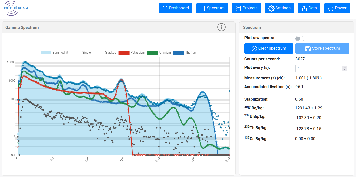
Spectrum view
Gamma Spectrum
The live spectrum is shown to check the spectral shape, energy stabilisation and the derived radionuclide concentrations (⁴⁰K, ²³⁸U, ²³²Th and optionally ¹³⁷Cs). When this page is opened the incoming as well as the accumulated spectra are shown in the figure. The accumulated spectrum (blue dots) is fitted using the calibration curves (the coloured lines, extracted from the calibration file) yielding (a) the blue "fitted spectrum" and (b) the concentrations of K, U, Th and Cs listed in the Spectrum block. The principles of the fitting procedure can for instance be found in the Gamman Software manual. Check the method of translating the measured spectrum to an energy scale and the method of extracting the nuclide concentrations by using standard spectra.
| Line | Description | Stored in your project? |
|---|---|---|
| Grey dots | Spectrum collected by the spectrometer stabilised to an energy scale | Yes |
| Blue dots | This is the accumulated spectrum by summing the grey dots | no |
| Red line* | The standard spectrum for ⁴⁰ K multiplied with the concentration shown in the Spectrum block | Individually for each measured spectrum |
| Green line* | The standard spectrum for ²³⁸ U multiplied with the concentration shown in the Spectrum block | Individually for each measured spectrum |
| Blue line* | The standard spectrum for ²³² Th multiplied with the concentration shown in the Spectrum block | Individually for each measured spectrum |
| Yellow line* | The standard spectrum for ¹³⁷ Cs multiplied with the concentration shown in the Spectrum block | Individually for each measured spectrum |
| Blue surface | The sum of the ⁴⁰ K, ²³⁸ U, ²³² Th and ¹³⁷ Cs lines. | No |
- The calibration spectra for these nuclides are extracted from the active Medusa Calibration File (MCF) that is present on the device. Calibration spectra are unique for each detector and cannot be interchanged between sensors.
Spectrum block
| Parameter | Description | Units | |
|---|---|---|---|
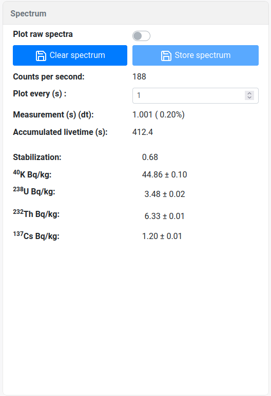 | Counts per second | Count rate from the last measured spectrum (grey dots) | counts per second |
| Plot every | An input value that accumulates spectra before plotting | seconds | |
| Measurement | The time the detector actually measured during the last recording. In brackets is the dead time (in percentage) of the measurement | seconds | |
| Stabilization | A parameter that describes the stabilization shift | - | |
| Accumulated live time: | The live time of the stacked spectrum (blue dots) | seconds | |
| Potassium (K) | The concentration ⁴⁰ K found (red line) | Becquerel/kilogram or % | |
| Uranium (U) | The concentration ²³⁸ U found (green line) | Becquerel/kilogram or ppm | |
| Thorium (Th) | The concentration ²³² Th found (blue line) | Becquerel/kilogram or ppm | |
| Cesium (Cs) | The concentration ¹³⁷ Cs found (blue line) | Becquerel/kilogram |