
The hardware
General working principle of the density sensor
The RhoC5 is a sensitive piece of equipment that contains a scintillation crystal. Use it as such, do not apply forces to the tube, and prevent it from physical shocks. The tip of the RhoC5 is made of nylon. This material is strong and wear-resistant, but remember that it can still break out of the aluminum tube.
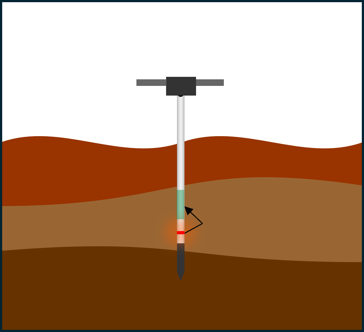
The figure above demonstrates schematically how the density measurement works. The small red disk contains a radioactive 22Na source with a low activity below the exemption value. This source will radiate gamma-rays into the soil. This soil will interact with these gamma-rays. One of the interactions that can occur is known as Compton scattering, where the direction and energy of the gamma-ray is altered. The green cylinder in the figure is a scintillation crystal that can detect gamma-rays when they interact with the crystal. Between the crystal and the source, a piece of tungsten is positioned. Tungsten has a very high density, which prevents most radiation from the source from reaching the crystal directly. The black nylon part at the bottom contains the moisture sensor. As a result, most radiation registered by the scintillation crystal has been scattered in the soil surrounding the RhoC5. With increasing soil density, more radiation will be scattered, and more gamma-rays will be registered. The RhoC5 has been calibrated to determine the soil density based on the number of gamma-rays detected per second.
What is in the box
The RhoC comes in a rugged case that contains a various parts.
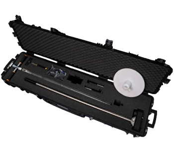
The RhoC5
Detachable handles can be screwed onto the device so that it can be pushed into the ground.
Dutch auger to prepare a hole that exactly fits the RhoC5
Hammer for driving the dutch auger in the ground
White PVC plate to hold the sensor at position and for depth measurement
Phone with app pre-installed as measurement device, including charger and cables
USB charging cable to charge the RhoC5
GPS antenna
Hardware set-up
To prepare the instrument for use, first screw the handles securely into the RhoC5 so that the unit can be positioned and pressed into the ground. Next, place the GPS antenna in its designated slot on the top of the sensor and ensure it is seated correctly. The power switch is also located on the top of the RhoC5. Switch the device on; the green PWR indicator LED will confirm that the instrument is operating. The RhoC5 is battery powered and can typically run for around six hours on a single charge.
LED indicators
The RhoC5 has 4 LEDs:
PWR: Shows power status
ETH: Indicates connectivity status
SCN: Raw spectrum collected
AUX: Auxiliary sensor input received
For general information on these LEDs, check the mDOS manual.
In addition, the PWR LED can be used to indicate power issues:
Description | Cause |
|---|---|
PWR LED blinks red 10 times before shutdown | Battery too low. Recharge. |
PWR LED blinks 2 to 6 times before shutdown | Issues with the battery. The temperature being too low is one of these issues, indicated by the PWR LED blinking 4 times. Starting the device in a warmer environment may resolve this issue. Please contact Medusa Radiometrics if the problem persists. |
All LEDs blink red 3 times | Issues with the battery management configuration, this should recover automatically. |
Charging
The charging connector on top is IP65 rated against dust and moisture, but only when mated with the connector or with the dust cap in place. Note that the detector should not be submerged. Charging a fully drained battery may take up to 3 hours. For this, a power delivery adapter is required, as such an adapter is capable of providing higher current and higher voltages than a typical USB adapter. Note that a standard USB adapter or power bank may not be capable of charging the RhoC5. Charging is only possible when the ambient temperature is at least 5 °C.
When charging, the LEDs on the hardware will indicate the charge progress:
0 - 25%: 1 LED blinking green or yellow
25% - 50%: 1 LED continuous + 1 LED blinking green or yellow
50% - 75%: 2 LEDs continuous + 1 LED blinking green or yellow
75% - 100%: 3 LEDs continuous + 1 LED blinking green or yellow
100%: 4 LEDs continuous
The color of the blinking LED indicates if the battery is charging normally (green), or slow (yellow).
Depth readings
The depth sensor uses radar technology to locate the top of the plastic baseplate. The position of the density sensor is calculated with respect to the bottom of the baseplate. Therefore, it is essential to always use the baseplate.
The depth provided is the center of the density measurement. The density measurement measures an average value over 50 mm layer of soil, so this is 25 mm below and 25 mm above the provided depth. In addition to the depth sensor, depth markers are engraved into the tube can be used to position the RhoC5, they can be read at the top of the white support plate where the tube exits. The markers are placed at intervals of both 5 cm and 2 inch.
The automatic depth reading has a maximum of 65 cm.