Theory
Mounting of a gamma-ray spectrometer
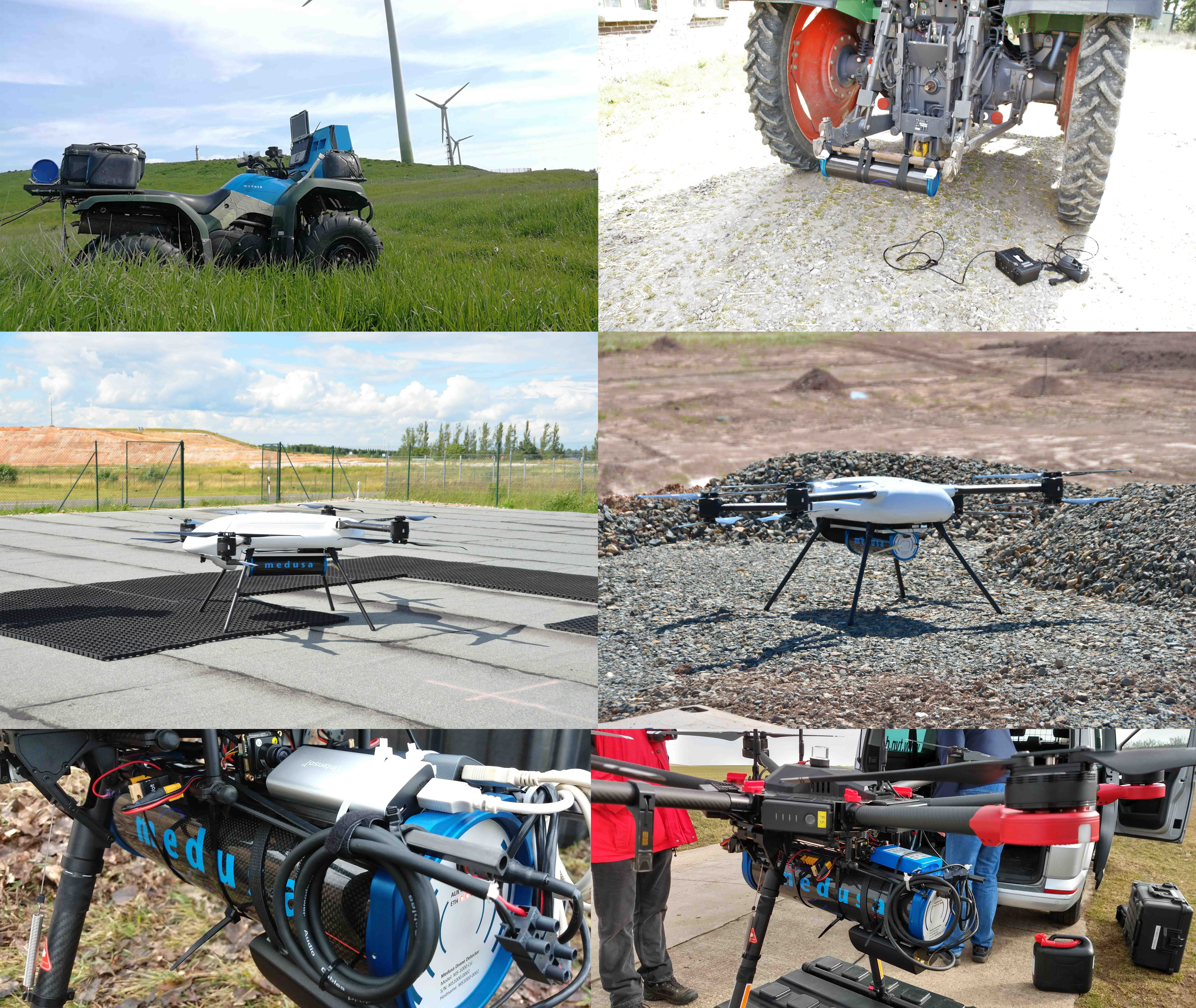
This page describes the principles of mounting a gamma-ray spectrometer. The spectrometer can be mounted on a quad-bike, a tractor, or a drone. Each device has its characteristics that implement the mounting uniquely. However, it should always adhere to the principles stated below. This page is intended to give information on the practical implementation of the mounting. Information on the theory and physical principles of gamma radiation can be found here: Measuring gamma radiation.
General considerations
In geophysical applications, the main point of interest is gathering knowledge from the soil and using gamma-radiation as a proxy for this. The spectrometer captures gamma radiation emitted by the soil beneath the detector. The standard calibration files provided by Medusa have been carefully tailored to analyze the situation where the heart of the spectrometer is placed at 80 cm above the ground.
Origin
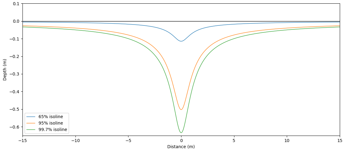
Radiation transport in the ground and air is a complex process for which we use Monte-Carlo simulations to establish our calibration files. However, to get an idea of the origin of the radiation that we measure in a detector, we can use the simplistic approach by only looking at the highest peak energy of the thorium-232 spectrum and see how the distribution of the origin of radiation is in the ground.

From the above picture, we see that about 90% of the radiation captured by the spectrometer originates from the top 60 cm of soil and a spot size of 10 m around the detector.
Attenuation
As described on the page Interaction of 𝛾-radiation and matter gamma-radiation is attenuated by material placed between the source (soil) and the detector. Therefore, it is preferential to mount the detector so that there is minimal material between the detector and the soil that will shield the signal emitted by the ground. If a material is placed between the source and the detector, the signal and registered concentrations of K, U, and Th will be structurally lower. The magnitude of this effect depends on the density and thickness of the material and the energy of the gamma-radiation. The formula below can be used to calculate the effect magnitude when the parameters are known, and the table gives some examples:
Material | Density (gm/cm3) | Thickness | Loss of signal (E=2.62 Mev (Th)) | Loss of signal (E=1.46 Mev (Th)) |
|---|---|---|---|---|
Air (dry) | 0.001225 | 80 cm | 0.39% | 0.51% |
Wood | 0.7 | 1 cm | 2.73% | 3.62% |
Plastic (pvc) | 1.2 | 0.5cm | 2.34% | 3.11% |
Aluminum | 2.7 | 0.2cm | 2.11% | 2.80% |
Steel | 7.8 | 0.2 cm | 5.98% | 7.89% |
Vibrations
The system has been designed for an industrial geophysical application. The CsI crystals at the core of most detectors can withstand shocks and rough usage. However, it is advised to minimize the amount of vibrations that the system has to endure to reduce risks and minimize unnecessary wear of the system.
Medusa provides all agricultural-type detectors with mounts and shock-absorbing rubbers that filter high-frequency vibrations. It is advised to mount the detector so that vibrations are minimized, and large shocks should be prevented.
If the detector is mounted without the supplied shock-absorbing mounts, for instance, under a drone, it is advised to place a soft material that will dampen the vibrations at the contact points of the mounts. For instance, in drone-borne mounting, it is recommended to place a piece of foam between the detector and the suspension of the drone.
More information on the mounting brackets supplied by Medusa can be found on our product support page.
Mounting
To conclude the mounting, it is advised to mount the sensor so that the sensor has a clear view and no material is present between the detector and the source of radiation. Furthermore, vibrations should be damped, and shocks should be prevented.
Some examples of mounting:

Validation of shielding
The vehicle that is used to mount the detector poses a minimal influence on the measurement. Some radiation is shielded by this vehicle, and therefore analysis will produce slightly lower concentrations than the actual values in the field. Medusa has established that in most applications, this influence is minimal (<5%) and can safely be neglected for most applications. However, the influence of this shielding can be measured for each mounting configuration by doing a set of two measurements. First, a static measurement at a certain position in the field has to be done while the detector is mounted on the vehicle. Then a second measurement has to be done where the detector is removed from the vehicle but placed at the same height without any shielding.
This measurement should be done where the ground underneath the sensor contains a homogeneous distribution of radionuclides. The measurement time is dependent on the desired accuracy. The difference in the results of the measurement will represent the shielding induced by the vehicle and these results can be used for the interpretation of the results of measurements where the detector is mounted on the vehicle.
