
Quick start
This getting started manual is intended to help you, our system's user, get up and running as quickly as possible. In other words - how do you mount the spectrometer on your measurement platform, what power do you need to supply, and how to perform a measurement.
Before starting
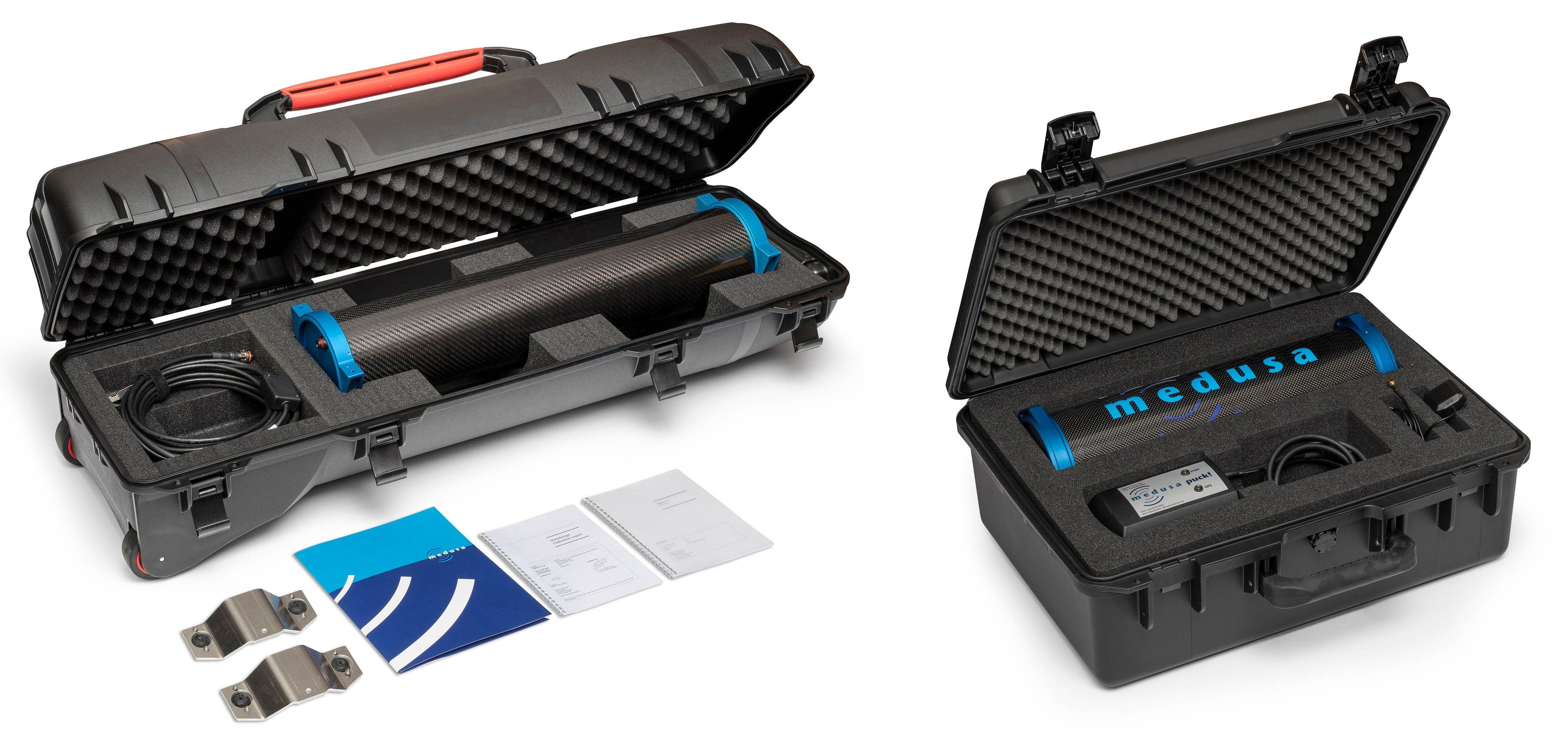
First, we want you to note that you have a delicate instrument in your hands. Our gamma-ray spectrometers contain a (relatively) fragile scintillation crystal at their core. This crystal and the device's electronics should always be handled with care. Dropping, hitting, or significant impact on the detector may result in the breaking of this crystal. Medusa has optimized the weight of the spectrometer systems while implementing a shock-absorbing layer that keeps the crystal stable. However, improper use could lead to breaking an element in the system. Therefore, it is crucial that the detector is handled with care and that proper preparation has been taken before working with this system.
UAV warning: You can use the detectors as drone detectors. However, testing with a dummy weight is advised to confirm that the UAV platform is suitable for this weight. Depending on the type of UAV you are using, the weight of this detector may be at the limit of what the UAV can handle. We have had many successful measurements with our detectors. However, before mounting the real detector, we always tested the platform with a dummy. There are reports of drones that crash when carrying their maximum load. This can have various causes, among which is the (weak) stiffness of the drones' frame (causing the IMUs to overcompensate) or magnetic interference (such as from little magnets incorporated in GPS antennas). Always make proper preparations when using the medusa spectrometer under a drone.
If you are in doubt about the mounting, handling or other handling issues, please contact Medusa. Our support section is always happy to help you out and give advice on the use of spectrometer systems.
Mounting the detector
The detector's end caps are equipped with mounting points. If appropriately fastened, these mounting points can support the detector's weight. The dimensions and mounting points differ between the different systems. Our technical section lists all the dimensions of the various Medusa detector systems. The MS-2000 detector can be mounted using the MSB-20x mounting brackets, whereas the smaller systems usually have an application-specific mounting.
Gamma-ray detectors are sensitive to radiation from all directions. Therefore, there is no "preferred" mounting direction - a sensor can also be mounted parallel to the direction of movement as perpendicular.
Matter between the detector and the radiation source attenuates gamma radiation. Therefore, the detector should be mounted so that there is the least possible obstruction between the source (the soil) and the sensor.
More information and examples of mounting the spectrometer on a platform can be found on the Theory page.
Powering the device
Medusa supplies the systems with a variety of cables specifically tailored for each application. The Cables and Connectors section provides information on the specifications of all available cables. The table below lists which cables come standard with each detector type. Always use Medusa-certified cables on the system; these cables are specifically designed for use with our spectrometer systems.
Detector | Commonly used Cable | Input voltage range |
|---|---|---|
MS-4000/MS-2000 | 9-35V | |
MS-1000-/MS-700/MS-350 | 5-35V | |
gSMS-100 | 9-35V |
Medusa spectrometers use 3W nominally and 6W at their peak power consumption. Make sure that the power source can supply this power. Most power banks can power the sensor. This power bank should supply at least 1.2 amperes at 5V to facilitate the 6W peak power usage.
A computer's USB port is not suitable for powering the detector because these ports can only supply 0.5 A
Configuring the measurement
When the system is powered, the spectrometer is automatically started. All data is logged and automatically saved to the last selected project.
System startup
The detector has four LEDs embedded in the top cap. The orientation of the LEDs relative to the connector depends on the detector series. Some sensors are mounted with the fastening wings down, such as the MS-2000, and some are mounted with the fastening wings up, such as the MS-350 or the MS-1000. The position described below is with the connector oriented below the LEDs. The table below lists the color coding for the mDOS V3.x systems.
Name | Colour | Function |
|---|---|---|
PWR | Green | Input voltage is ok and in the right input range. |
Red | Input voltage is too low. | |
Red blinking | Blinking at 1hz means the input power could not be measured. | |
Blue | Input voltage is too high, possibly damaging the internal electroncis. | |
Purple | Input voltage has large fluctuations, please check the power supply. | |
ETH | Green | Ethernet cable is connected. |
Blue | The sensor has a connection to the internet. | |
SCN | Yellow | A raw spectrum is collected. |
Green | A raw spectrum is stabilized, analyzed, and stored. | |
AUX | Yellow | A PTH reading is collected and stored. |
Green | A GPS reading is collected and stored. | |
Blue | An auxiliary reading is collected and stored (external sensor) |
If both the SCN and AUX LEDs blink in red, the internal storage is almost full. When all storage space is taken, the default action is to overwrite the oldest data. At a typical data logging rate of 1Hz and storage capability of 16GB, you can store around 80 days of continuous data recording.
Accessing the mDOS interface through the built-in website
When an Ethernet cable is connected
The detector can be accessed either by directly connecting the detector to a computer or by connecting it to a network using a router. The detector will check if it receives an IP address from a router. If your router provides no IP address, e.g., when the detector is connected directly to a computer, the detector will initialize with its default IP address. If a router in the network provides the detector with an IP address, this address must be determined by checking the router settings. Most routers can set a unique IP address based on the connected device. Detectors in the network can also be found using the Medusa detector finder tool.
Additionally, if your network supports multicast DNS (mDNS), the detector can be accessed using the detector hostname.
To access the built-in website, navigate to the IP address in a browser.
Setting | Description | Example |
|---|---|---|
Standard IP-address | 192.168.2.150 | |
Hostname | <Model>-<Series number>.local | MS-2000-0054.local |
Web server | <IPaddress> | 192.168.2.150 |
When the detector is connected directly to the computer by using the Ethernet cable, the website of your detector can be accessed by navigating to the address 192.168.2.150:8000 (mDOS V2) or 192.168.2.150:3333 (mDOS V3)
Through WIFI
Connecting your computer, tablet, or phone to the detector's network makes it possible to access the web server through its standard IP address, as described in the section above.
Setting | Description Internal puck (PUCK-300) |
|---|---|
Detector SSID | MS<version>-<serial> |
Detector password | @Radiometrics123 |
Web server | 192.168.3.1 |
When you encounter difficulties accessing the spectrometer using a phone or a tablet, it might be necessary to turn off your data connection.
The landing page of the web-interface
Selecting or downloading a project
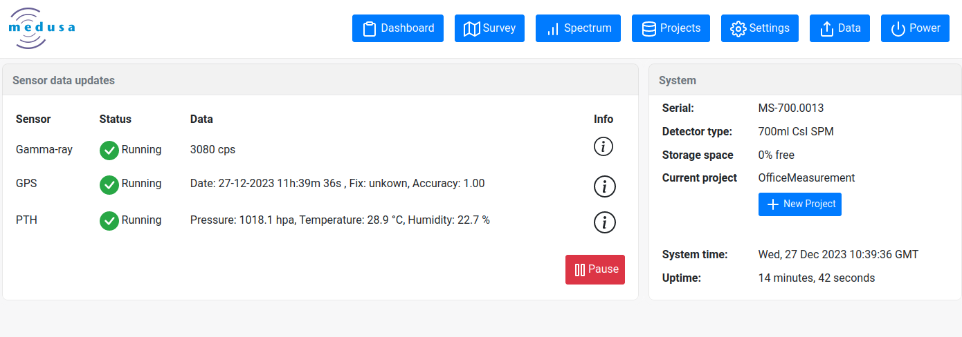
When connected to the interface, inspect the measurement through the available pages. The project page gives basic information on the current measurement and selected project.
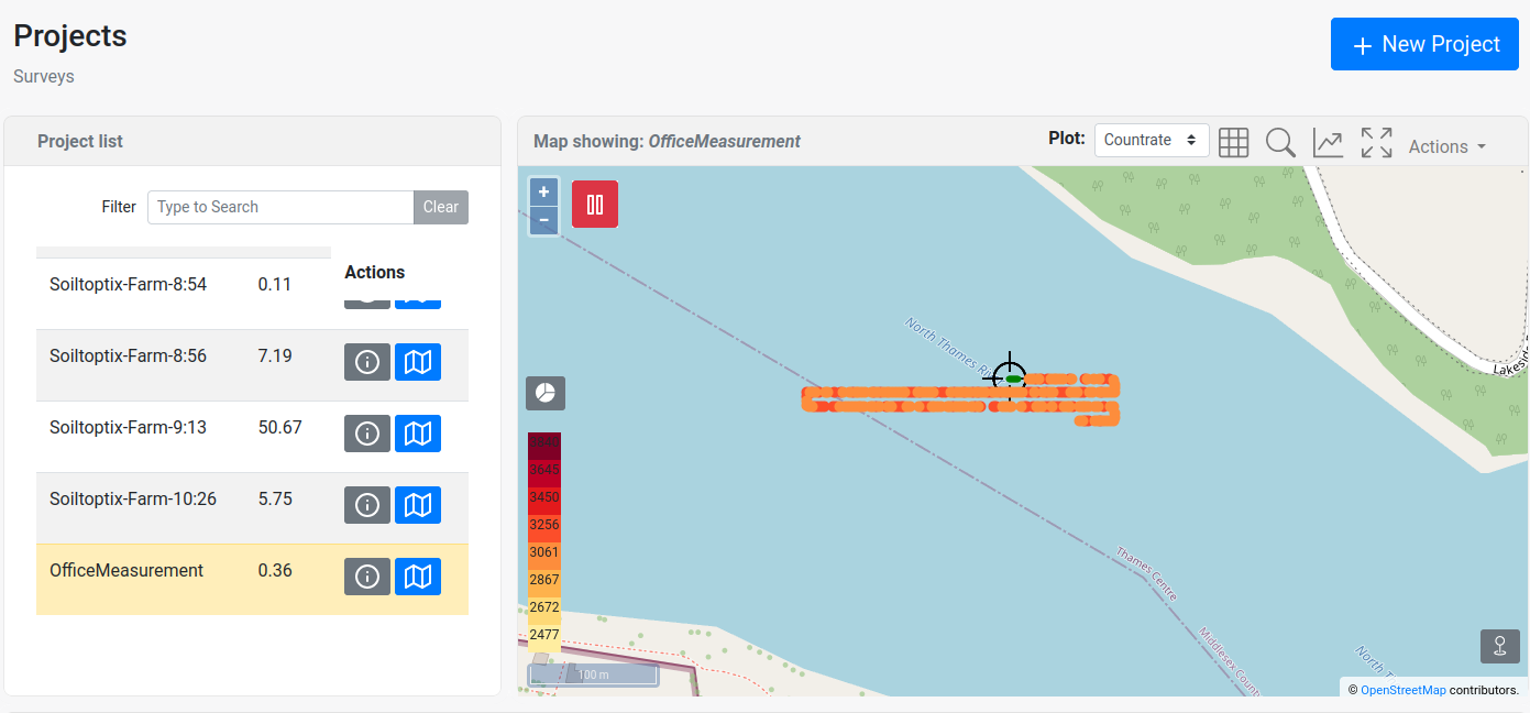
Project management (projects page)
New projects can be created, or old projects can be selected or deleted. Selecting means that data will be logged into this project. Deletion of the project is permanent and cannot be undone.
Starting a measurement
After selecting a project, the measurement is started. Because the spectrometer is designed to be "always on" the data is stored automatically on the device. Once a project has been created, all data is subsequently logged to this project. The Medusa Gamman Software provides the tools to make selections on the project. This can be done either by timestamp or by geometric position.
It can be confirmed that the measurement is still running by checking the LEDs during the measurement. The SCN LED will blink for every stored spectrum, and the AUX LED will blink for every auxiliary data entry.
Retrieving the data
After or during measurement, you can download the recorded data from the device. This must be done through the web interface by navigating to the projects page. A project can be downloaded by clicking on the project name and then using the download button. When downloading a project, it will be compressed to a .zip file before sending it to the user. A progress bar shows the progress of the compression. Once this is finished, a pop-up will appear with the project file. You can now save the data to your PC or other devices.
A downloaded project contains raw data, including data from the spectrometer and auxiliary equipment, such as the GPS and PTH sensors. This dataset also contains analyzed data that output radionuclide concentrations. Furthermore, the download also includes a CSV file that contains georeferenced radionuclide concentrations that can be directly used in map-making software.
The downloaded radionuclide concentrations are analyzed using the parameters set on the spectrometer. If needed, the raw data can be loaded into Gamman for (re)processing with different analysis parameters.
Turning the device off
Powering down the system is done by simply removing the power.