

Appearance
1. Overview
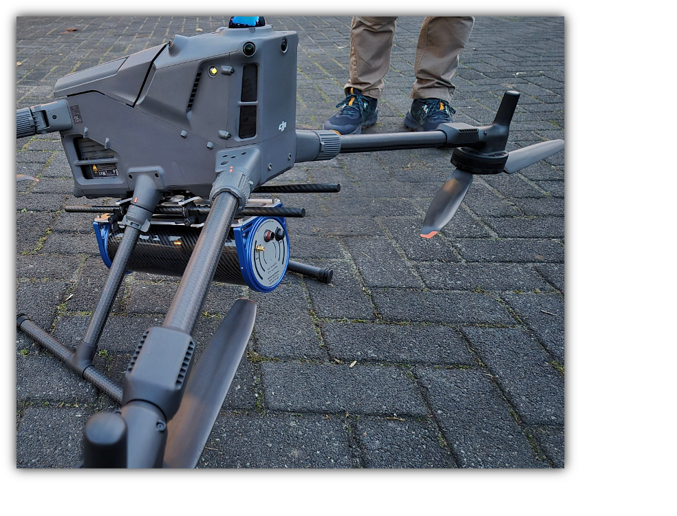
The MSB-303 mounting system is a modular and generic mounting solution designed for Medusa detectors equipped with a 100 mm carbon fibre tube interface.
The system enables quick and secure installation of the detector onto measurement platforms. While the DJI Matrice 350 and DJI Matrice 400 are used as reference platforms in this manual, the MSB-303 is not limited to these drones. Any drone or carrier platform capable of supporting the payload and providing a suitable mounting interface can be used. This is achieved by attaching Part A (drone plate) to the platform using an appropriate mechanical interface.
The mounting system consists of two primary components:
Part A – Drone Plate
Aluminium plate with integrated carbon fibre rods, mounted to the drone or carrier platform.Part B – Sensor Plate
Aluminium plate mounted directly to the Medusa detector.
These two components form a quick-release interface, enabling fast installation and removal in field conditions.
2. General Notes and Safety
The carbon fibre tubes are intentionally supplied longer than required. The additional length is to accommodate the carrying of additional modules such as height sensors using these rods. Cut them to the desired length based on your application.
Insertion of the carbon tubes into the rubber mounts may require force. This interference fit is intentional and ensures a secure, vibration-resistant connection.
Always use thread-locking compound (e.g. medium-strength) on all screws to prevent loosening due to vibration.
Ensure the drone is powered off during installation.
When working with inverted drones, always protect sensors and antennas from mechanical damage.
3. Assembly Instructions – Drone Plate
3.1 General Procedure (All Platforms)
The following principles apply to all drone platforms:
Attach Part A (drone plate) to the drone using:
Existing mounting holes, or
A custom adapter plate if required.
Ensure:
The mounting surface is rigid and flat
The load is evenly distributed
Fasteners are properly secured with thread-lock
After mounting the plate:
Insert the carbon fibre tubes into the rubber dampers using a twisting motion
Ensure equal protrusion on both sides
4. Assembly Instructions – DJI Reference Platforms
4.1 Installation on DJI Matrice 400
Preparation
Remove the (Dual) Gimbal connector from the front of the drone.
Required Parts
| Part | Amount |
|---|---|
| DJI Matrice 400 | 1 |
| MSB-303 Drone plate (consisting of two parts: Part A: aluminium plate with carbon fibre rods mounted to the drone, Part B: an aluminum plate mounted on the Medusa detector. | 1 |
| Carbon fibre tubes | 2 |
| unthreaded spacers M3x16 | 4 |
| Screws M3x25 | 4 |
Procedure
- Place the drone upside down to simplify installation.
Note: Ensure all sensors are protected before doing so. - Install the M3 spacers into the designated mounting holes.
Info
Note:
The spacers are intentionally 1 mm shorter than the nominal height. This creates preload in the assembly, improving stiffness and reducing vibration.
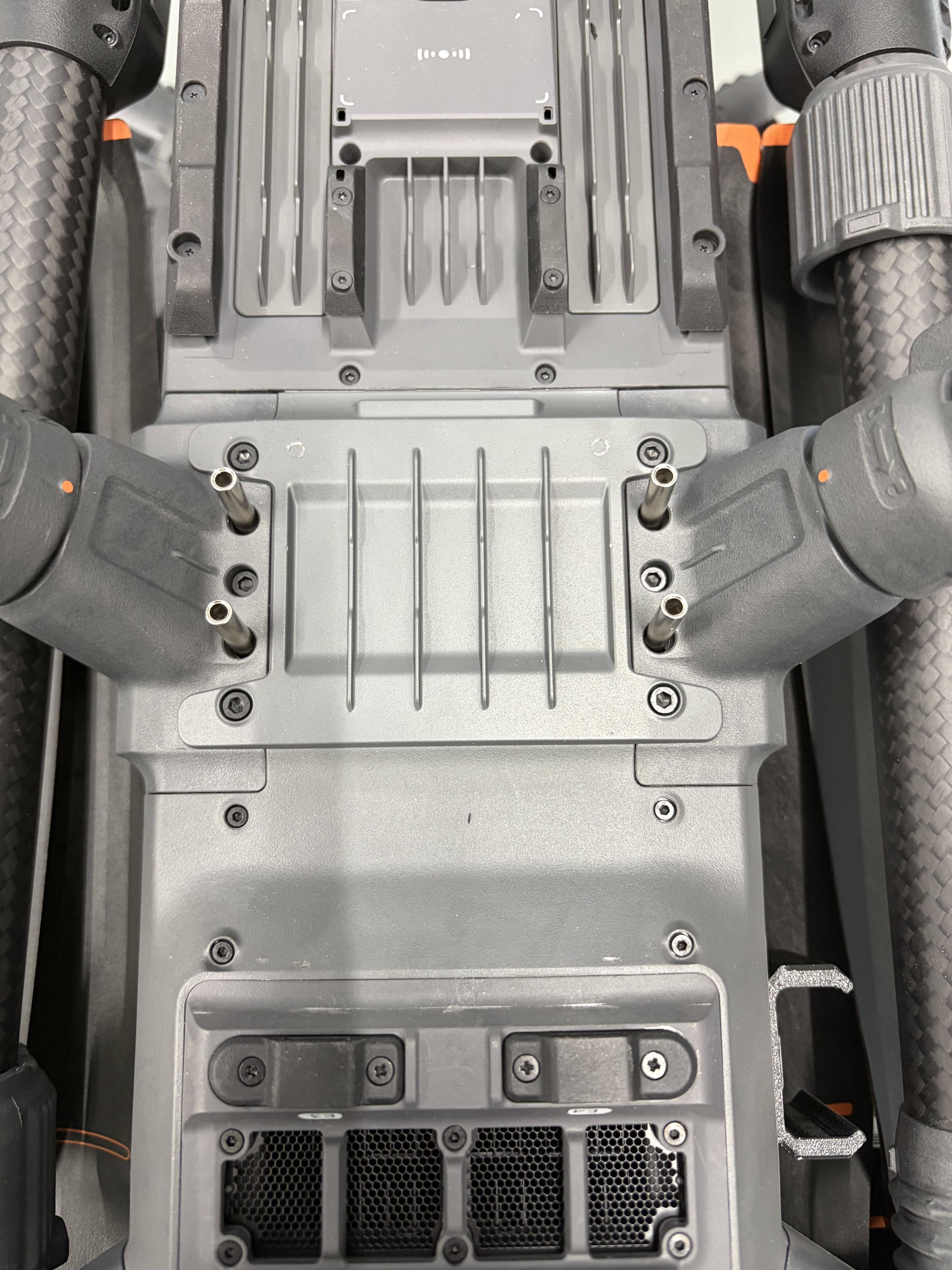 Placement for the Standoffs
- Position the drone plate on top of the spacers.
- Insert the M3x25 screws and tighten them in a cross pattern.
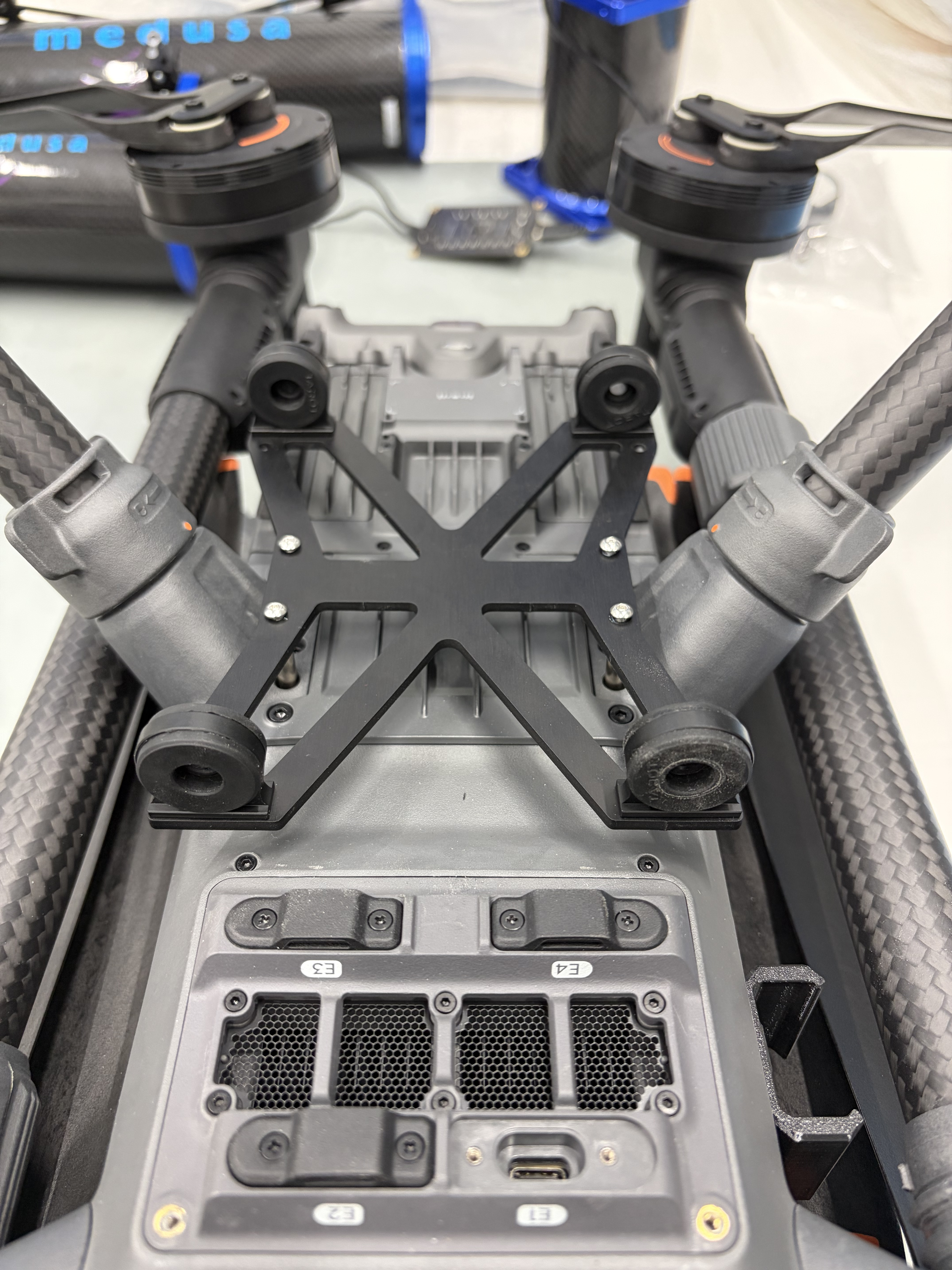 Drone plate and screws placed and screwed in
Insert the carbon fibre tubes into the rubber mounts:
Use a twisting motion
Apply steady pressure
Ensure symmetric extension on both sides
Installation of the drone-side assembly is now complete.
Make sure to disable the downward sensors as described in the final remarks section below.
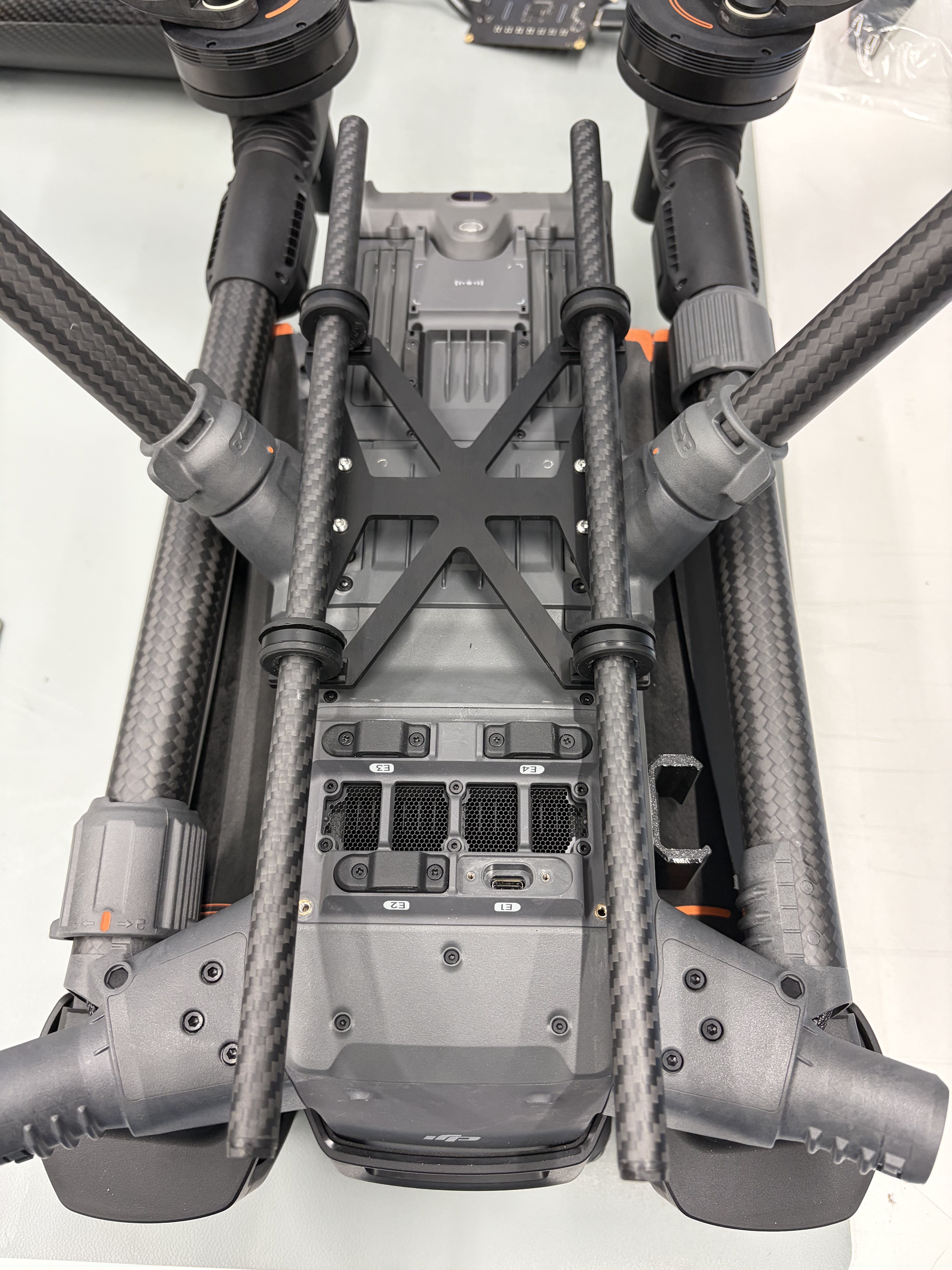 Drone plate completely mounted
Note
When using this mounting in combination with the SkuHub provided for the SPH Engineering radar altimeter, note that the radar altimeter is typically attached to the front-mounted gimbal connector. This position is incompatible with the mounting system described here.
In this configuration, the radar altimeter should instead be installed on the carbon fibre rods using the 3D-printed adapter shown below.
4.2 Installation on DJI Matrice 350
Preparation
Remove the Gimbal connector from the front of the drone. Alternatively, see the comment below to reduce the length of the carbon rods
Required Parts
| Part | Amount |
|---|---|
| DJI Matrice 350 | 1 |
| Drone plate | 1 |
| Carbon tubes | 2 |
| Stand-offs M3x10 | 4 |
| Screws M3x10 | 4 |
Procedure
- Place the drone upside down on a soft surface.
- Install the M3 stand-offs into the mounting holes.
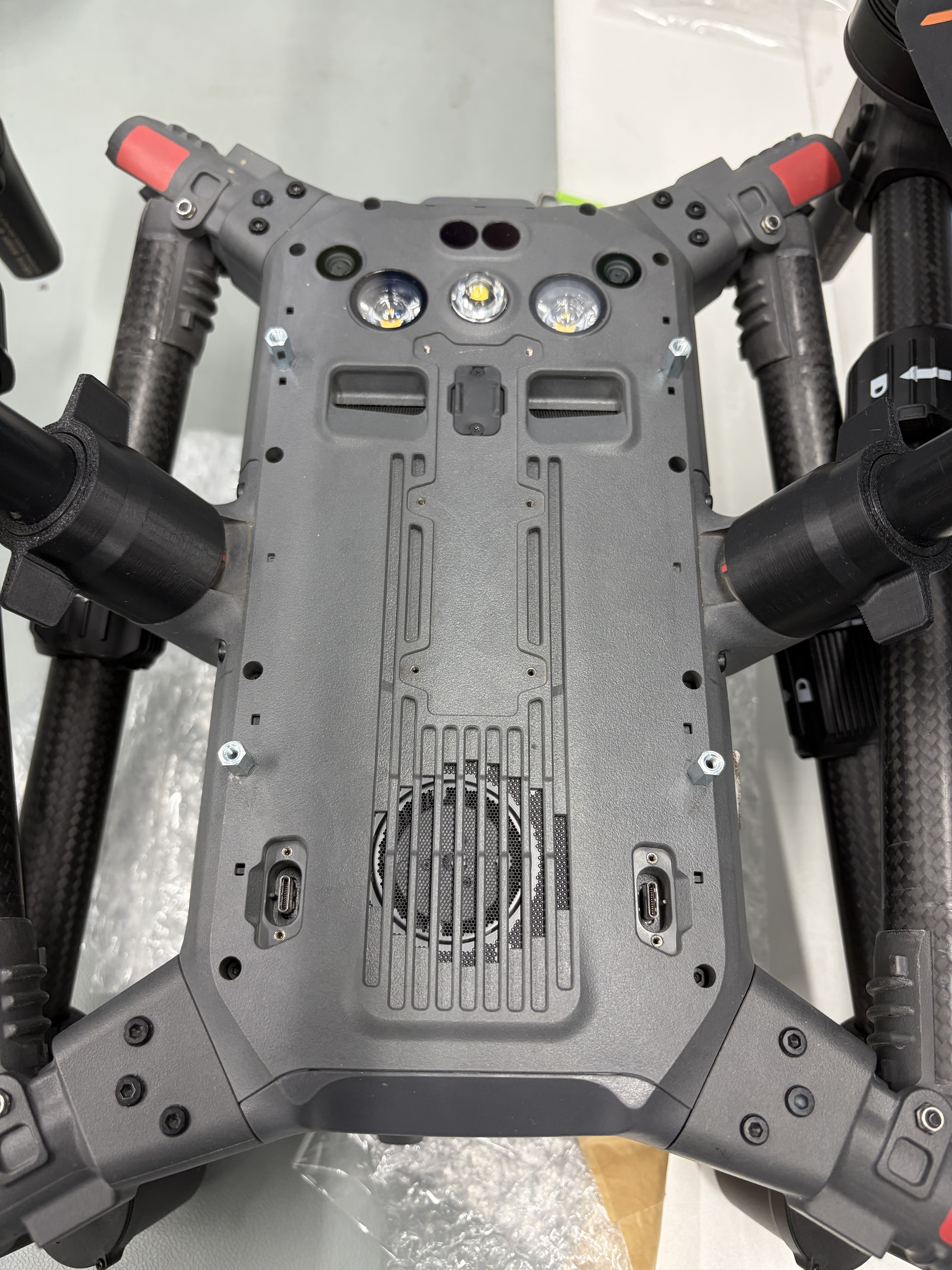 Standoffs screwed in the mounting holes
- Position the drone plate on the stand-offs.
- Insert and tighten the M3x10 screws in a cross pattern.
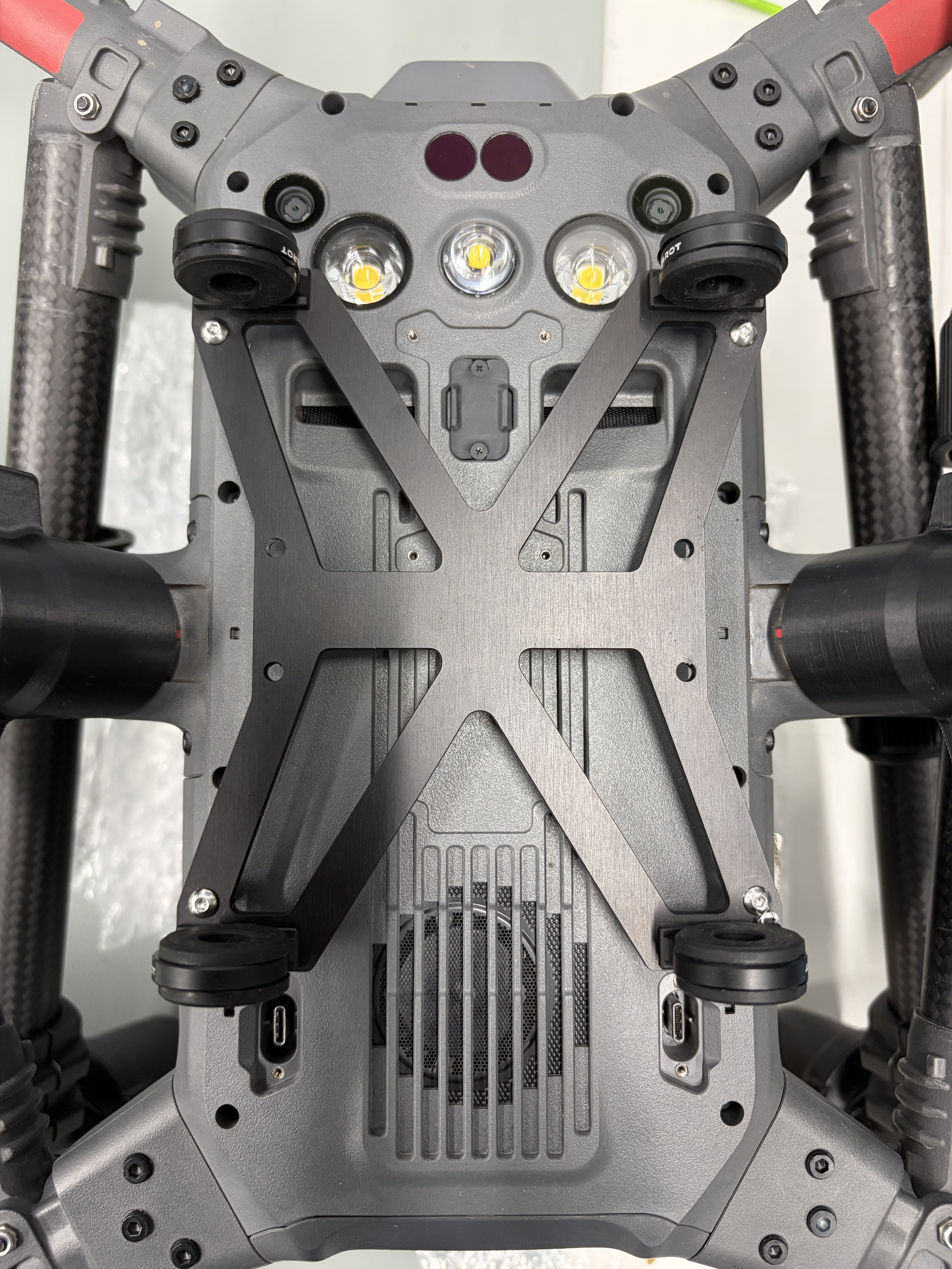 Drone plate attached to the drone
Prepare the rubber mounts:
- If required, create a small pilot hole in the center
Insert the carbon fibre tubes using a twisting motion.
Ensure equal tube extension on both sides.
Installation of the drone-side assembly is now complete.
Make sure to disable the downward sensors as described in the final remarks section below.
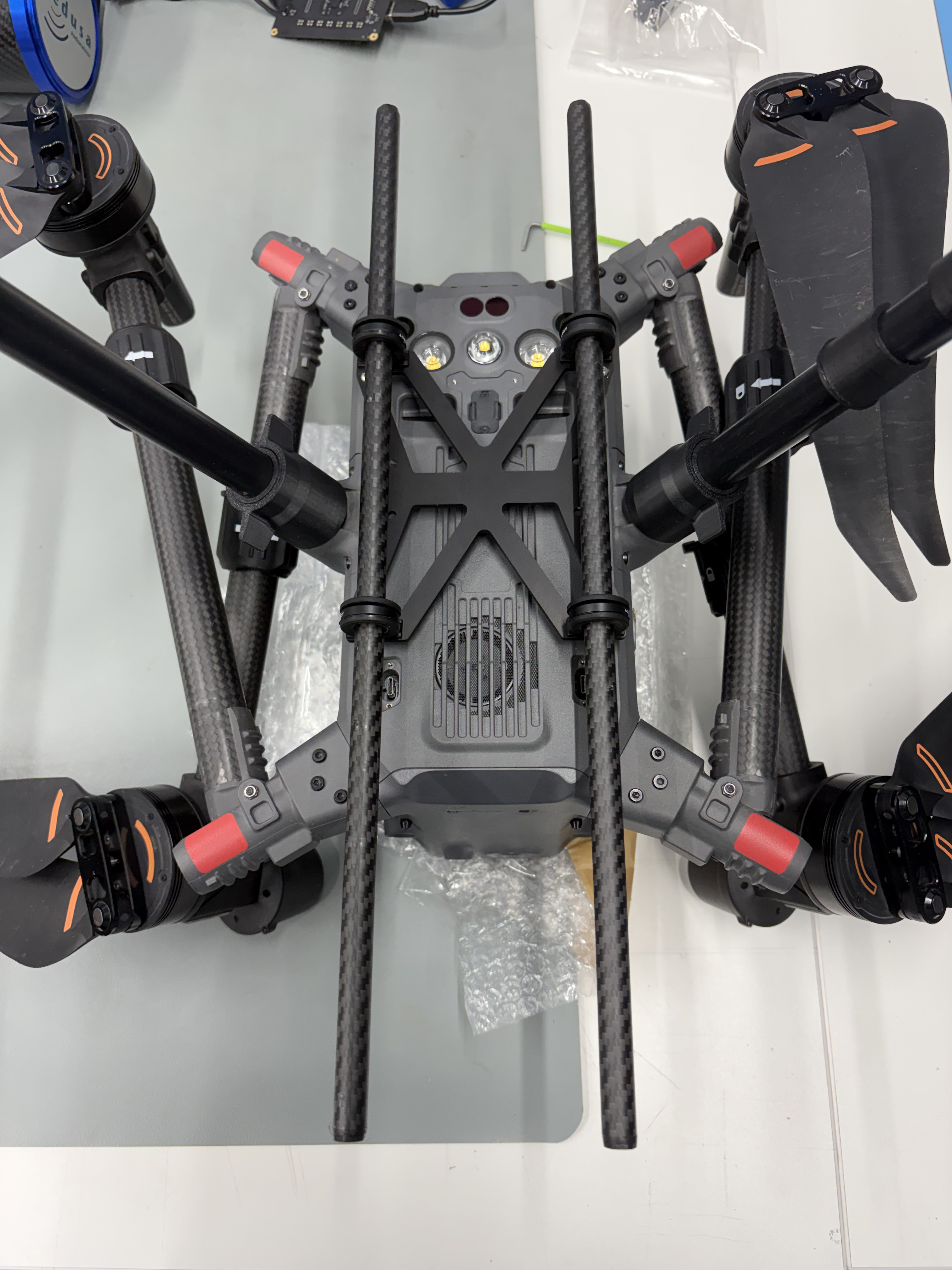 Drone plate completely mounted
Note
When using this mounting in combination with the SkuHub provided for the SPH Engineering radar altimeter, note that the radar altimeter is typically attached to the front-mounted gimbal connector. This position is incompatible with the mounting system described here as it is delivered.
For the DJI M350 there are two options:
- Reduce the length of the carbon rods so that the Gimbal Connector can be left on the drone.
- Alternatively, the radar altimeter can be installed on the carbon fibre rods using the 3D-printed adapter listed below.
5. Assembly Instructions – Sensor Plate
Required Parts
| Part | Amount |
|---|---|
| Medusa detector | 1 |
| Sensor plate | 1 |
| Corner pieces | 4 |
| Lock nut M4 | 4 |
| Washer M4 | 4 |
| Screws M4x20 | 4 |
Procedure
Prepare the corner pieces:
Insert one M4 lock nut into each corner piece
Ensure the nut is oriented downward
Place a washer on top
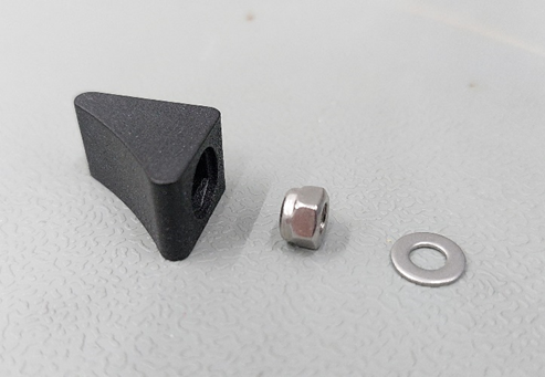 Corner pieces orrientation
Insert the corner pieces into the detector end caps.
Important:
Ensure washers remain properly seated.
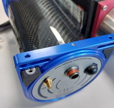 Corner pieces in place
- Position the sensor plate on top of the detector.
- Secure the assembly using M4x20 screws.
- Tighten all screws evenly.
The sensor-side assembly is now complete.
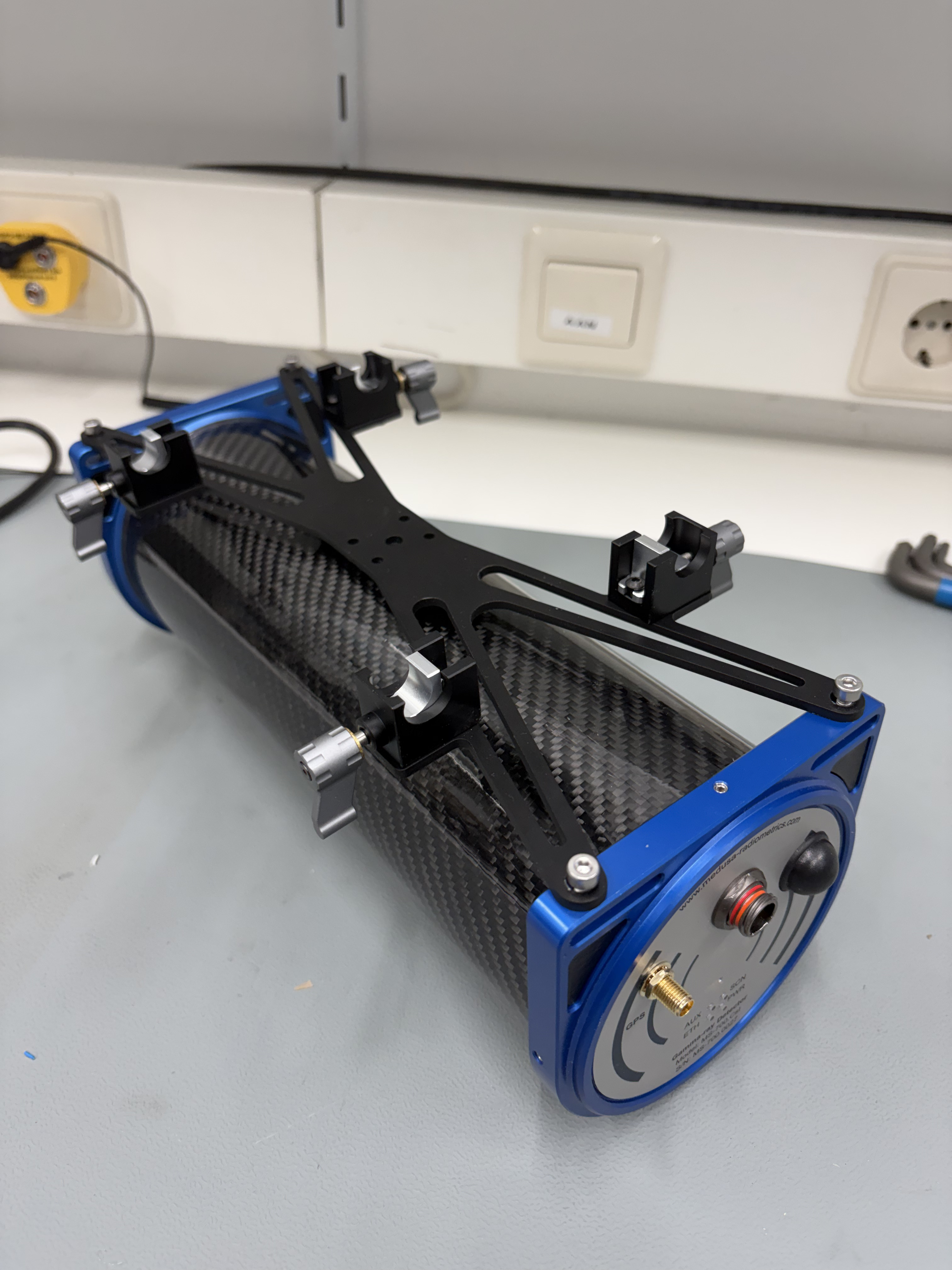 Sensor plate completely mounted
6. Optional – Powering the Detector via Drone
The mounting system supports integration with the DJI E-Port V2 interface.
The E-Port module can be mounted on the carbon tubes between the rubber dampers
Secure using the integrated thumb screw
Connect to one of the drone’s E-Port interfaces
This allows the detector to be powered directly from the drone platform.
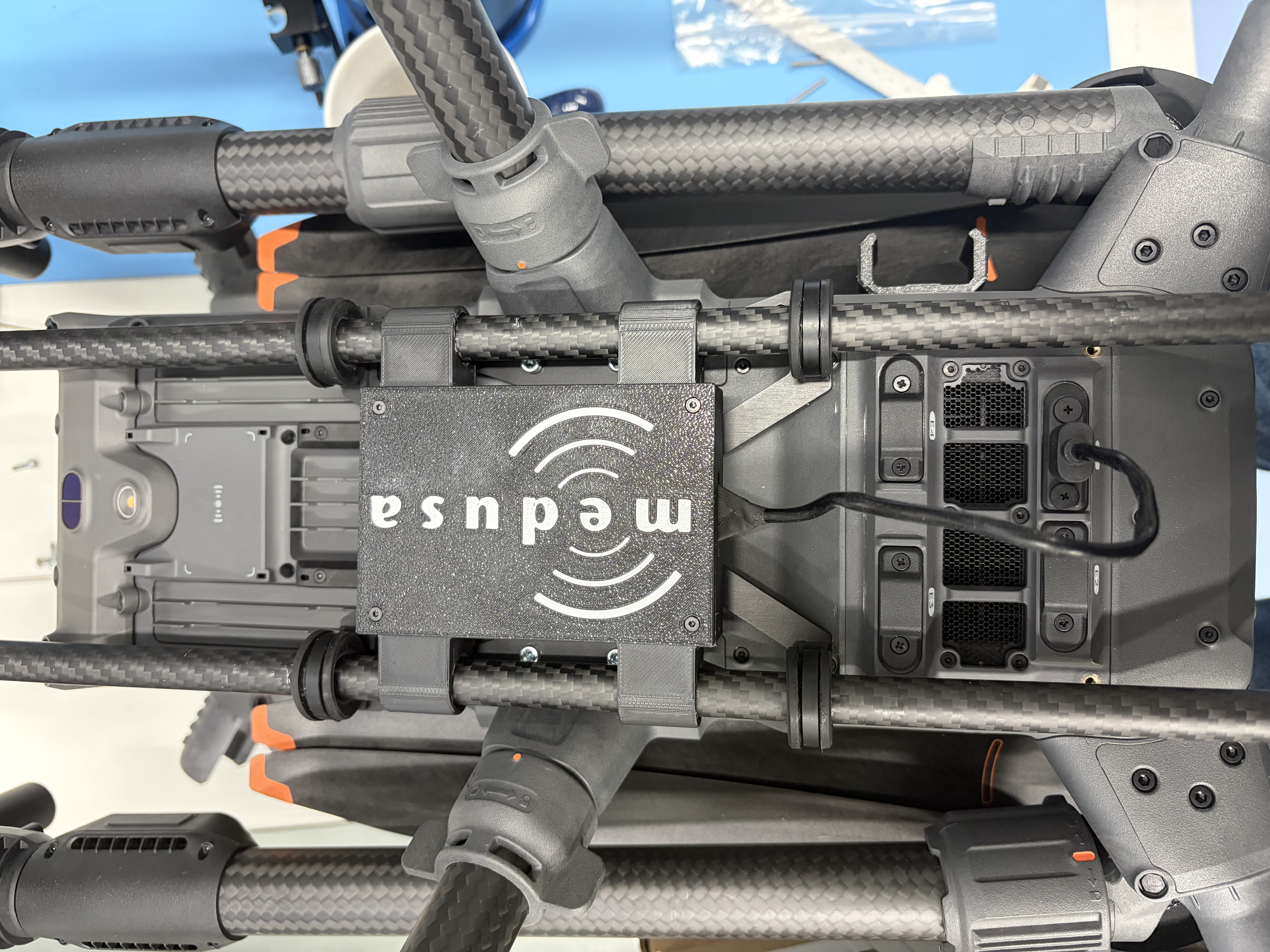 DJI E-Port V2 kit mounted in place
7. Mounting and Dismounting the Detector
Mounting Procedure
- Loosen all thumb screws (counter-clockwise).
- Align the sensor assembly with the carbon fibre tubes.
- Press the sensor assembly onto the tubes until it clicks into place. Important:
Apply force on the mounting system, not on the drone frame. - Tighten all thumb screws (clockwise).
- Ensure all four attachment points are fully secured before releasing the detector.
Dismounting Procedure
- Support the detector manually.
- Loosen all thumb screws.
- Pull the sensor assembly off the carbon tubes.
 Video on how to mount the sensor
8. Final Remarks
Always verify mechanical integrity before flight.
Perform a short test flight after installation.
Regularly inspect rubber dampers and fasteners for wear.
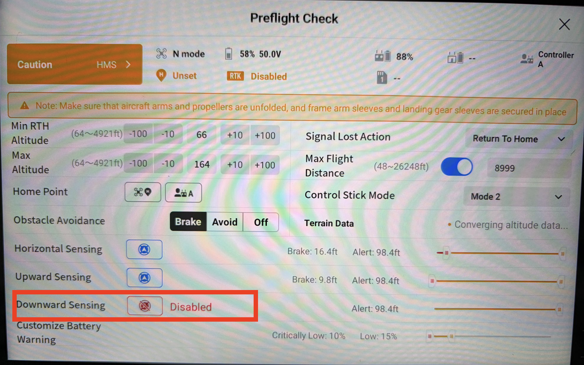
Make sure the downward-facing sensors are disabled before takeoff. Otherwise, the drone may refuse to take off because the sensors detect obstacles beneath the aircraft. To disable the downward sensors, open the camera view on the remote controller and turn off the downward sensing option. The image below shows the settings when the downward sensors are turned off.
Dimensions and weights
In the attachment you will find some document about the posistion of the mounting holes if needed.
| Size mount | Drawing | DXF | Weight (including parts and screws) |
|---|---|---|---|
| Part A: Drone plate | MSB-303 Part A - Drone plate.pdf | MSB-303 Part A - Drone plate.dxf | 126 gram |
| Part B: MS-100 | Drone plaat MS-100 Drawing.pdf | Drone plaat MS-100 V3.3.dxf | 162 gram |
| Part B: MS-350 | Drone plaat MS-350 Drawing.pdf | Drone plaat MS-350 V3.3.dxf | 168 gram |
| Part B: MS-700 | Drone plaat MS-700 Drawing.pdf | Drone plaat MS-700 V3.3.dxf | 176 gram |
| Part B: MS-1000 | Drone plaat MS-1000 Drawing.pdf | Drone plaat MS-1000 V3.3.dxf | 202 gram |